Figuring out what hardware version of the Raspberry Pi you are using

So you are spending the night messing around with your Raspberry Pi’s and forgotten what version you are using, instead of having to take the cover of the RPi or walk over to the closet, to see what version it is, you can do this remote from the command line.

From the command line issue the following command:

cat /proc/cpuinfo

output should be something like this:

processor       : 3
model name      : ARMv7 Processor rev 4 (v7l)
BogoMIPS        : 38.40
Features        : half thumb fastmult vfp edsp neon vfpv3 tls vfpv4 
CPU implementer : 0x41
CPU architecture: 7
CPU variant     : 0x0
CPU part        : 0xd03
CPU revision    : 4

Hardware        : BCM2835
Revision        : a02082
Serial          : 0000000000000000
pi@bifrost:~ $

look for the part in the bottom saying Revision (in my case it’s a02082)

now use the following list to fire out what hardware it is.:

Code Model Revision RAM Manufacturer

900021

A+

1.1

512MB

Sony UK

900032

B+

1.2

512MB

Sony UK

900092

Zero

1.2

512MB

Sony UK

900093

Zero

1.3

512MB

Sony UK

9000c1

Zero W

1.1

512MB

Sony UK

9020e0

3A+

1.0

512MB

Sony UK

920092

Zero

1.2

512MB

Embest

920093

Zero

1.3

512MB

Embest

900061

CM

1.1

512MB

Sony UK

a01040

2B

1.0

1GB

Sony UK

a01041

2B

1.1

1GB

Sony UK

a02082

3B

1.2

1GB

Sony UK

a020a0

CM3

1.0

1GB

Sony UK

a020d3

3B+

1.3

1GB

Sony UK

a02042

2B (with BCM2837)

1.2

1GB

Sony UK

a21041

2B

1.1

1GB

Embest

a22042

2B (with BCM2837)

1.2

1GB

Embest

a22082

3B

1.2

1GB

Embest

a220a0

CM3

1.0

1GB

Embest

a32082

3B

1.2

1GB

Sony Japan

a52082

3B

1.2

1GB

Stadium

a22083

3B

1.3

1GB

Embest

a02100

CM3+

1.0

1GB

Sony UK

a03111

4B

1.1

1GB

Sony UK

b03111

4B

1.1

2GB

Sony UK

b03112

4B

1.2

2GB

Sony UK

b03114

4B

1.4

2GB

Sony UK

c03111

4B

1.1

4GB

Sony UK

c03112

4B

1.2

4GB

Sony UK

c03114

4B

1.4

4GB

Sony UK

d03114

4B

1.4

8GB

Sony UK

c03130

Pi 400

1.0

4GB

Sony UK

a03140

CM4

1.0

1GB

Sony UK

b03140

CM4

1.0

2GB

Sony UK

c03140

CM4

1.0

4GB

Sony UK

d03140

CM4

1.0

8GB

Sony UK

See More here:

https://www.raspberrypi.org/documentation/hardware/raspberrypi/revision-codes/README.md

Udskift din TDC Homebox med et modem.

This Article is in danish as it’s primary readers are danish.

TP-Link TD-W9970:

14/06-2024: Efter en omgang torden igen så døde min Askey RTV1800-D79, DSL line driver var toal smeltet og printet skadet så meget at det ikke kunne repareres, jeg har desværre ikke haft held med at source en ny, så alternativet til et modem blev en TP-Link TD-W9970 som er en all-in-one enhed som heldigvis supportere at sætte den i bridge mode.

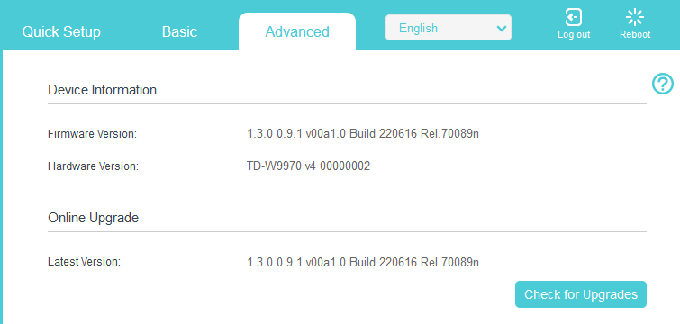
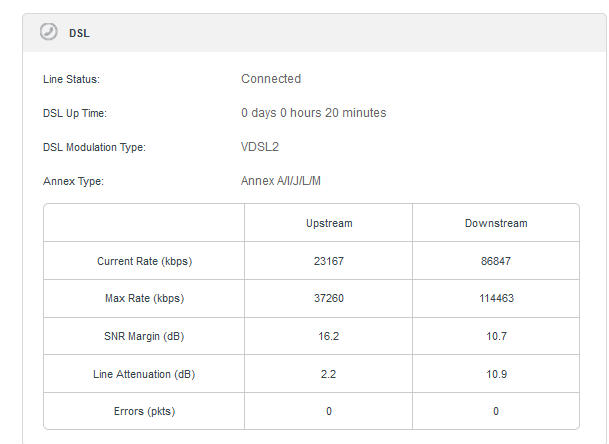
Selve firmware og hardware version kan ses her:OBS: den viste firmware kan ikke findes hvis man går på TP-links hjemmeside og går til deres danske sektion, men derimod kan man se den hvis man tager den internationale, selvom firmwaren er tagget som en EU version.

Mit setup ser således ud og virkede ud af boksen:

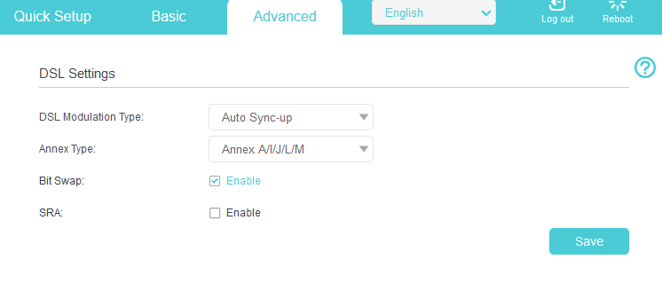
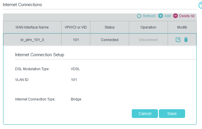
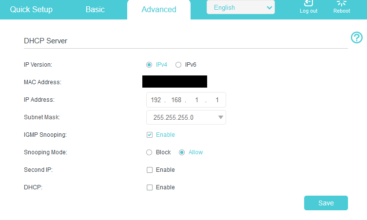
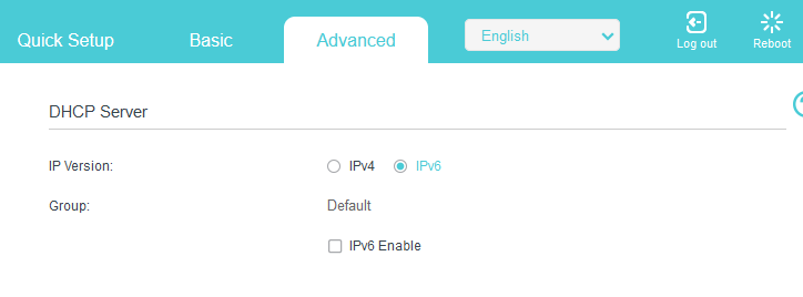
Note: Jeg kørte hurtigt igennem den setup wizard og har som sådan kun lavet små ændringer som at slå DHCP serveren fra samt IPv6 på lan siden, og sætte Annex typen og vlan til 101 som beskrevet i Askey sektionen.

Advanced -> Network -> DSL Settings
Advanced -> Nework -> InternetAdvanced-> Network -> LAN-Settings -> IPv4Advanced-> Network -> LAN-Settings -> IPv6Linjen linket op i første hug:

Askey RTV1800-D79:

22/05-2018 updated: Jeg har smidt min seneste version fil op, efter at jeg måtte sætte et nyt modem op grundet at den Zyxel jeg egenlig have skiftet over til døde efter overspænding på porten og tog en del andet udstyr med i faldet, så snart jeg har en ny Zyxel så smider jeg config op til denne :).

Jeg har i flere år brugt mit eget modem på min TDC ADSL2+ forbindelse (20/2Mbit), i forbindelse med omlægning til en 40/10Mbit forbindelse, blev jeg konverteret til en VDSL2 forbindelse, mit god gamle netgear DM111 ADSL2+ modem, skulle derfor udskiftes til noget som kan forstå VDSL2.

Jeg havde ved et held fået et TDC VDSL2 modem (Askey RTV1800-D79), dette modem understøtter iht. til TDC’s lister både Vectoring, SRA, samt G.INP, hvilket burde sikre driften i langtid.

OBS: jeg har godt nok telefon på mit abb. men jeg bruger det ikke, så disse noter drejer kun om at få internet igennem.

i min naivitet troede jeg at der ikke var forskel på en modem løsning og en router løsning (Homebox), dette viste sig dog at der var stor forskel.

følgende er de settings jeg er bekendt med:

Homebox:
VLAN ID = 101
QOS = 1
VLAN MUX
PTM IPoE

Modem:
VLAN ID = 50
QOS = 0
VLAN MUX
PTM IPoE

Modem settings er fisket ud ved at tilgå http://192.168.1.1 på modemet, Homebox settings er fundet å TDC’s forum.

for at tilgå modem, skal det lige have et spark over benet ved at reset det, hold reset knappen inde indtil at alle lamper blinker, gør dette nogle gange (det kan godt drille), forsøg derefter at tilgå den på 192.168.1.1, når det lykkes skuælle den gerne komme op og spørge om login, her bruger du admin som bruger og password.

man kan via modemet hive settings ud, men umiddelbart ikke ændre noget på denne, dette kan man dog workaround ved at redigere den fil man får ud af settings, jeg ligger hermed min originale fil op samt den redigeret fil som fik min forbindelse til at virke.


Original settings fra modem (TDC Setup): TDC_setup_org.zip

Orginale setting fra modem (Hiper Setup): Hiper_setup_org.zip

De settings jeg kører med idag: working_final_160203.zip

UPDATE nye settings: working_final_180522.zip

NB: Filerne er pakket som ZIP filer, da det gav lidt problemer med encodningen og er derved lige til at smide på boksen.

God fornøjelse med at få det til at spille 🙂

den primære ændring er:

Orginal:

<WANIPConnection instance=”1″>
<Enable>TRUE</Enable>
<ConnectionType>IP_Bridged</ConnectionType>
<Name>br_0_1_1</Name>
<ExternalIPAddress notification=”2″>0.0.0.0</ExternalIPAddress>
<X_BROADCOM_COM_IfName>ptm0.1</X_BROADCOM_COM_IfName>
<X_BROADCOM_COM_ConnectionId>1</X_BROADCOM_COM_ConnectionId>
<PortMappingNumberOfEntries>0</PortMappingNumberOfEntries>
</WANIPConnection>

Modificeret version:

<WANIPConnection instance=”1″>
<Enable>TRUE</Enable>
<ConnectionType>IP_Bridged</ConnectionType>
<Name>br_0_1_1</Name>
<ExternalIPAddress notification=”2″>0.0.0.0</ExternalIPAddress>
<X_BROADCOM_COM_IfName>ptm0.1</X_BROADCOM_COM_IfName>
<X_BROADCOM_COM_ConnectionId>1</X_BROADCOM_COM_ConnectionId>
<X_BROADCOM_COM_VlanMux8021p>1</X_BROADCOM_COM_VlanMux8021p>
<X_BROADCOM_COM_VlanMuxID>101</X_BROADCOM_COM_VlanMuxID>
<PortMappingNumberOfEntries>0</PortMappingNumberOfEntries>
</WANIPConnection>

Jeg vil sandsynligvis skrive mere her ved lejlighed, når jeg får mere tid til at kigge på settings.

How to fix/hack the Samsung CLX-3175FW, imaging unit

Well the place where i do some voluntary work, had this Samsung CLX-3175FW Color Laser printer for some years now and the unit i starting to show to following warning: “replace imaging unit soon” from the old days doing repairs on different printers at the university, i found that a lot of manufacturers place small fuses, software counters that are supposed to make the user replace different parts in the printers normally these parts are quite expensive, some of these “errors” can sometimes be reset without that much work, and the this was one of them.

What you needs is the following:

A Solderings iron

A 56Ω 0,25watts resistor

Let’s get to work.First thing is to take all the color cartridges out of the printer and place them somewhere safe (be sure not to drop the color powder on anything)

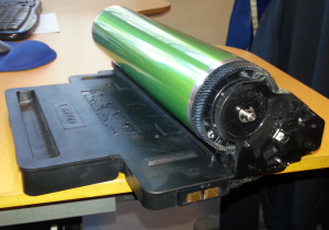
next thing is to remove the wast toner box in the left side, now remove the imaging unit.

image_unit_samsung

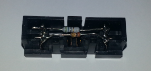
you should se 2 cobber contacts in the right side of the imaging unit, this small device can be removed from the unit.

resisitor_samsung

inside the unit that i took apart, there where 2 resistors, the small one, is actual just a  “sense” function that makes the printer aware if the unit is not installed, in my case the resisitor was a 140KΩ, the larger resistor was a 56Ω but this resistor was burned and did no longer function. So this resistor functions as a “new” device put into the printer, the printer then burns this resistor to reset the imaging unit counter.

a quick trip to the storage with a new 56Ω resistor, i removed the old one and soldered the new inside the unit, i used a 1% resistor as this was the only type that i had.

i then put the unit back into the imaging unit, and cleaned the unit for any excess toner, and dust.

then i put everything back into the printer and powered the unit on.

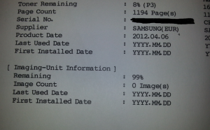
i printed a report for the unit and wolia 🙂 the printer now thinks the imaging unit is new.

report_samsung

i den took the unit apart again and checked the resistor, somehow the printer didn’t burn i properly so i remove the resistor , just to be sure that i didn’t break anything, maybe the original samsung placed resistor is easer to burn?, but hey what the heck it did the job.

This fix/hack cost around 0.50DKR, and a new imaging unit cost around 900-1100DKR so witch one do you chose?.